|
Explanation of this document is applied to the newest version.
|
 A network and a pin


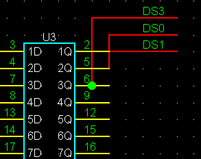
The conditions which a network generates from a pin are only the points of the outside of a pin.
That which exists in the middle of a pin does not become a network even if it connects at a junction.
By a diagram, the network of DS3 is not connected to six pins of U3.
DS1 is connected to 2 of U3, and DS0 is connected to 5 of U3, respectively.
The operation method, a request, a question, etc.
 fwgf3995@mb.infoweb.ne.jp
It passes.
This page is translated with translation software from Japanese.
Go Top


 A network and a pin


 fwgf3995@mb.infoweb.ne.jp
It passes.