|
Explanation of this document is applied to the newest version. |
| D2 CAD | What's New | Manual | Image screen | Revision history | Download |

|
Explanation of this document is applied to the newest version. |
| D2 CAD | What's New | Manual | Image screen | Revision history | Download |
| Let's input. |
|---|
| 1) Line input |
| 2) Character input |
| 3) Parts input |
| 4) Pin input |
| 5) Circle input |
 The input of a character

With a menu, a tool bar, or the pop up menu of a right click, if a character is chosen, it will become the character input mode. If a character input finishes, let's change to the line input mode or the selection mode.


|
The input of a character |
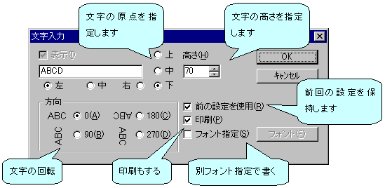
When carrying out a character input, a character input is chosen and the left button of a mouse is pushed in the place on which it is drawn on [ no ] the schematic.
Then, since a dialog is displayed, please input a character and a parameter. |

|
Character height | Please be careful not to make [ many / not much ] the size of a character, since a display will become slow if a kind is increased. |

|
Cautions |
If a character input is completed, we will recommend you to change into the input mode of a wire.
If it is still this mode, edit of a double click will not function well. |

|
The character with a bar |
A character display of negative logic is possible for D2 CAD.
In order to attach a bar on a character, it is then. It is used before and after a character to attach "~" to. Only a head is OKed when attaching all. Example 1~ABC~/DEF If it writes, a bar is attached on ABC. example 2) If it is written as ABC/~DEF~, a bar is attached on DEF. (The last "~" is omissible) If it is written as example 3~AB~CDE~F~, a bar is attached on AB and F (the last "~" is omissible). |
 fwgf3995@mb.infoweb.ne.jp
It passes.
This page is translated with translation software from Japanese.
Go Top